
The BSA Dandy made its debut at the 1955 Earls Court show but was not available to buy until 1957 due to engineering development delays. It remained in production for 6 years. By the time I rode my first, battered Dandy, they had probably been out of production for 2 or 3 years. It sold in reasonable numbers but was not the success it might have been because of the competition and a number of shortcomings touched on below.
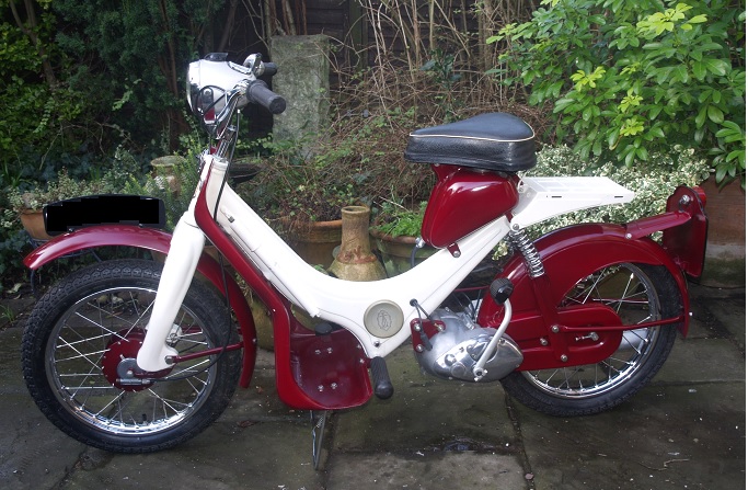
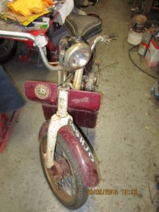
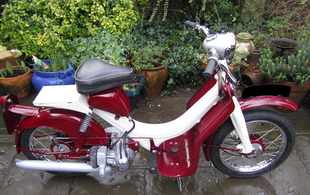
My restored BSA Dandy is shown above. The BSA Dandy is fitted with 15″ x 2.5″ wheels. It makes use of a pressed steel frame with a large plastic grommet on the lower left-hand side providing access to the internal cable runs and space for a tool kit. The frame supports the rubber mounted leg shield giving protection from the elements. Front suspension is via a leading link arrangement with the springs mounted inside the front leg. The rear suspension is achieved by two plain springs beneath the rear of the petrol tank, with the whole of the engine and bike rear end pivoting about the upper-most engine bolt. There is no shock absorbing on the Dandy and so the ride is a little bouncy to say the least, though not unpleasant in my view. The ride is helped by the generous saddle that pivots forward to reveal the petrol tank filler cap which includes a two-stroke oil measuring cylinder.
The handlebar controls are fairly conventional except for the left-hand twist grip gear change which includes a thumb extension on its right-hand side to provide a bit more leverage. The Dandy has two gear ratios but makes use of an unorthodox method of changing gears. For example, on Lambretta or Vespa scooters of that era, the gear change was achieved by pulling in the clutch lever and then rotating the complete lever and handlebar grip assembly forward or backwards to the next position. The Dandy, in contrast, uses a conventional clutch lever mounted on the handlebars together with a rotating twist grip gearchange that needs a pre-selector gearbox.
In the Dandy scheme, the next gear is (pre-) selected by first rotating the twist grip to the required position (first, neutral or second) but, it’s only when the clutch lever is pulled in, that the actual gear change takes place. It sounds like a clumsy way of doing a gear change but it becomes a little more natural after practice. Unfortunately, because there is no control of the speed at which the gear change actually takes place using this approach (it depends on the strength of the selector tube springs as described below), gear changes can be a bit harsh. I assume that the reason BSA did not adopt the Italian approach to changing gears was simply down to cost considerations.
The Dandy uses either Wipac or Lucas electrics which led to the use of a number of different configurations for the headlight. The electrics on mine are Wipac which has only the lighting switch mounted along with the speedometer in the top of the headlight shell. The horn button and headlight dipper switch are mounted in a combined switch next to the throttle. In contrast, the dipper switch for the Lucas electrics is mounted next to the lighting switch in the headlight shell and only the horn button is mounted on the handlebars.
In general, the Dandy uses a main/dipped headlight and pilot light in the headlamp and two lighting bulbs in the rear light. The reason for this is that the normal headlamp and one of the rear bulbs was used when the engine was running, and the pilot light and the other rear bulb was used when the engine was switched off. In this latter mode, power was provided by two small 3V Type 800 batteries housed inside the headlight shell.
I believe the early Dandys did not have a speedometer since its maximum speed was only about 30 mph. Most had the speedometer mounted in the headlight shell with the speedometer drive unit bolted between the left-hand side of the front wheel hub and the left suspension link. However, others had the speedometer mounted on a bracket at the back and near the top of the left side of the leg shield. The speedometer drive cable was peculiar to the Dandy and is much thinner than the standard type and also used non-standard sized knurled nuts. Unfortunately, these are now impossible to get hold of.
The Dandy makes use of a 70 cc single cylinder two-stroke engine which has a U-shaped configuration to fit either side of the back wheel. The chain guard is bolted to the left-hand side of the engine and a blade is bolted the right-hand side, providing the arms which support the back wheel. The rear mudguard is also bolted via stays and a U-shaped bracket.
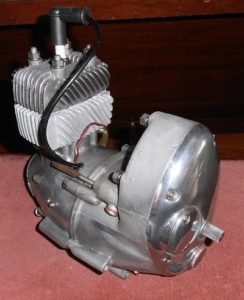
The engine consists of two halves bolted together down its centre line. The right-hand side contains the cylinder together with the Wipac or Lucas generator. The left-hand side contains the clutch and the gearbox. The Dandy uses a small Amal 365 carburettor with a hand operated choke which cleverly fits inside an outer cover on the right-hand side of the engine giving the engine a relatively neat, uncluttered outer appearance.
The Dandy’s crankshaft makes use of a roller bearing big end with the crankshaft bearings located inside the left-hand crankcase. Unlike many other two strokes, the Dandy does not rely on the oil in the fuel mixture to lubricate the bottom end of the engine. Instead, this is lubricated by grease held in place by 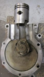 suitable seals on the crankshaft. On the earlier Dandys, there was no easy way of re-greasing the crankshaft bearings. Fortunately, on later Dandys like mine, 2 small tubes were provided from the outside of the crankcase to the centre of the crankshaft bearings allowing the grease to be topped up. The grease nipple and screw at the end of these tubes can just be seen bottom left in the engine picture.
The single plate clutch uses 6 clutch springs, each of which is held in place via a cap and cotter pin. The driving plate with friction material on either side is sandwiched between the clutch backing plate and the pressure plate. The driving plate has a set of metal dogs built into it which project towards the flywheel in the opposite side of the engine. These mesh with corresponding dogs projecting from the flywheel and allow the engine power to be transmitted to the clutch driving plate.
The ignition is provided by an ignition coil that is part of the generator assembly which includes the flywheel rotor. Unfortunately, the contact breaker points are also mounted within the generator under the flywheel, leading to one of the Dandy’s m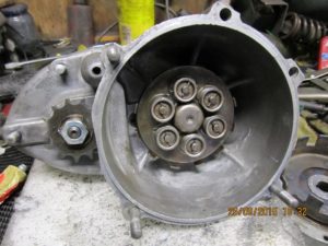 ain shortcomings. This was that, in order to get at the points during a service, the engine first had to be removed from the bike, spilt into its two halves, and then the flywheel removed. This must have added at least an hour or two to the time taken to do a basic service and therefore increased the cost accordingly. The Dandy was not unique in this feature but it definitely belied the original claim in the literature from the 1955 Earls Court show that the Dandy was easy to service!
The gearbox internals are shown with the outer, right hand cover removed. The two sets of pinions for the two-speed gearbox can be seen in the middle an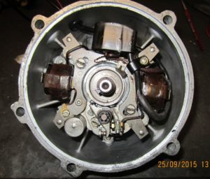 d to the right in the picture. Beneath the right-hand pinion is a sliding dog operated by a single selector fork attached to the tube in the top of the picture. The selector fork tube is moved in and out of its tunnel via the gear change cable, moving the selector fork and sliding dog at the same time to change gear. However, the gear change cable does not do this directly but, instead, does it via a spring-loaded inner tube. It’s only when the outer selector tube is unlocked, as described below, that the inner tube springs push the outer tube and selector fork to the required gear change position.
The clutch cable is attached to a horizontal arm connected to the left-hand end of the spring-loaded rod shown at the top of the picture. When the clutch lever 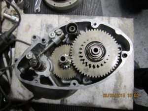 is depressed, the rod rotates and performs two functions. The first is to depress the clutch operating rod below the adjuster on the left-hand side thereby disengaging the clutch. In addition, it also rotates the gearchange locking arm at the right-hand end of the rod.
The end of the gearchange locking arm has three grooves corresponding to the three possible gear change positions (first, neutral and second). The selector fork, in turn, has a spade extension which engages with one these grooves to lock the selector fork and sliding dog in the required position. When the clutch lever is pulled, the locking arm is rotated out of the way and releases the selector fork spade. When this happens, the selector tube, selector fork and sliding dog are then free to move laterally, under spring pressure from the inner selector fork tube, to the correct position for the next gear.
In practice, the adjustment of the gear change cable free play is very critical if the correct selection of all the gears is to be achieved. To do the adjustment, the small inspection plate in the gearbox outer cover needs to be removed to allow the end of the gearchange locking arm and selector fork spade engagement to be seen. Adjustment is achieved using the large adjuster on the gearbox end of the gear change cable. This needs to be screwed in or out until all three gear change positions are reliably achieved as seen by looking at the end of the gearchange locking arm.
Finally, the gear teeth that engage with the kickstart quadrant can be seen above the right-hand pinion. My later Dandy has a conventional, foot operated kickstart lever that is probably best operated standing off the machine with the right leg. I also own an ex-army Armstrong MT500 with a Rotax engine which is infamously equipped with a left-hand kickstart and, I for one, have never been able to operate this sitting on the machine with my left leg. Surprisingly, the earlier Dandy’s were equipped with a much longer, hand-operated kickstart lever that rested pointing forward just in front and towards the right-hand side of the left-hand footrest. Presumably, this was meant to be operated more easily when sitting on the machine after it had stalled but was clearly a nonsensical arrangement and was dropped early on.
My Dandy Restoration
 I own quite a few BSA motorbikes, most of which have been restored to factory condition. My main interest is in 1960’s and 1970’s BSA motorbikes at the moment, with a particular passion for single cylinder variants, having started motorcycling on a Triumph Tiger Cub followed by a BSA C15. I also have a love of ex-army motorcycles, but that’s probably another story!
Nevertheless, I have always had a fascination for the BSA Dandy after regularly riding a very battered one on waste ground while still a delinquent teenager. I remembered the fact that it had a 2-speed pre-selector gearbox that I recall as being very awkward to use and probably the worst type to try to learn to ride a motorbike on. Until recently, I had only ever seen BSA Dandys abandoned in ditches and hedge rows which is probably where a large number of them ended up. In fact, I do not ever remember seeing one on the road.
Despite a few initial misgivings, I decided that I had to add a BSA Dandy to my growing BSA collection. Surprisingly, they crop up relatively frequently on eBay and I was able to pick one up in relatively good condition at a satisfyingly low price. In addition, the Seller only lived a couple of miles away which was a great bonus. Unlike all the previous bikes I’ve bought, which required the effort of hiring and collecting a trailer, this one came apart very easily with a small selection of tools and then fitted easily into the back of my car.
Although the same is probably true for a lot of much older bikes, availability of spares for the BSA Dandy is relatively poor, bordering on non-existent in most cases. In general, it’s not possible to get new engine spares, off-the-shelf control cables or new 15″ wheel rims. For anyone contemplating restoring a BSA Dandy, the clear advice is to buy one in nearly complete condition with a good exhaust system. Second-hand spares do crop up on eBay but many seem to be offered at exorbitant prices on the basis that rarity means people will pay a lot of money for them. For example, a very badly battered silencer was offered, not so long ago, at the price I bought my bike for. A carburettor was more recently offered at around £200!
Fortunately, my Dandy did not need many spares. The main items missing were the speedometer and its drive together with the carburettor which the owner’s son had inexplicably taken to Australia where he lived. However, this was posted back to me a few weeks later. I then managed to get a NOS speedometer from a dealer I met at the Kempton Park auto jumble and then bought a very rare Dandy NOS speedometer drive on eBay.
 Restored 1957 BSA Dandy
It took about 3 months to restore the Dandy, mostly determined by the time taken to get the necessary re-chroming done. This re-chroming was relatively expensive because of the large number of chrome parts on the bike, including the wheel rims. In order to save a bit on cost, I decided not to go down the usual shot blasting and powder coating route but instead to do all the paint removal and spray painting myself. To this end, I am particularly grateful to RS Paints for being able to supply the correct BSA Devon Red and Ivory paint colours for my particular Dandy.
Restored 1957 BSA Dandy
The bodywork was largely in good condition and was suffering only from superficial rust in most places. The main exception was the floor of the leg shield that, unfortunately, was rusted through from underneath where a strengthening plate was spot welded to take the load from the centre-stand. This plate was replaced and the leg shield repaired making the whole assembly almost as good as new. The rear mudguard also needed welding/brazing in places where it had either split or where mounting holes had enlarged because of rusting.
The Dandy seat still had its original covering but the pan was rusting and needed attention. The seat was, therefore, dismantled to allow the pan to be re-painted before the original foam and cover were re-assembled. I normally get RK Leighton to re-do my seat covers but, in this, case I decided it was much more sensible to retain the original cover for authenticity reasons. However, I had to fabricate the missing brass plaque mounted on the rear of the seat and to add the correct BSA logo on to it.
The engine was in relatively sound condition with a good (previously re-bored) cylinder bore and piston rings, both still within an acceptable wear tolerance. The cast iron cylinder had a broken fin but this was easily repaired with a bit of careful welding. Along with the silencer, the cylinder was given a few coats of high temperature aluminium paint which was the original finish on these items. All the engine seals and any bearings not in good condition were replaced. The engine uses a single plate clutch that was in surprisingly good condition for its age, as were the clutch springs. Fortunately, the gearbox sprocket was also in good condition especially as a replacement would have been very difficult to find.
Restoring the wheels was reasonably straightforward. Normally, I replace the original rims with new ones but, in this case, they are simply not made in the required size any more so re-chroming was the only option. The bike actually came with 2 spare wheels and so I choose the least rusty pair for the restoration. New stainless spokes were purchased from Central Wheel but it turned out to be more like re-spoking a pushbike wheel than a normal motorcycle wheel, with the small diameter nipples being a bit of a challenge.
The brake shoes showed very little wear and so were re-used. Unlike most other motorbikes that I am used to, the Dandy’s hub bearings are similar in configuration to those of a pushbike with separate ball bearings and cones used. The tricky part was to adjust the free play in the bearings which can only be done effectively using the hand adjuster on one side of the hub.
One of the biggest problems in this restoration was in getting replacement control cables, including the gear change cable – these are not available off-the-shelf. None of the original cables was in a particularly complete condition and so it was impossible to work out exactly what their correct dimensions were. However, with a bit of help from BSA forum members, I was able to find out the overall lengths of the cables but, unfortunately, not the required free play. I, therefore, had the cables specially made by JJ Cables but with less free play than I knew would be required. When I came to fit them, I had to adjust the free play by carefully trimming the length of the outer cables in order to end up with the correct functionality. The biggest challenge was in doing this for the gear change cable since the way this fits at either end is quite involved.
In my view, the BSA Dandy must rank along with the Triumph Tiger Cub as one of the most delightful looking machines produced in that era. My Dandy restoration was reasonably straightforward with only the poor availability of spare parts making this challenging in certain areas. In terms of restoration costs, this was not a cheap machine to restore, mainly because of the amount of re-chroming necessary. Despite this, in its restored state, my Dandy is probably worth a little bit more than I paid out in total and I am certainly happy to include this in my growing collection of BSA motorcycles.
BSA Dandy Specifications
- Year: 1957-62
- Engine: Single cylinder, 2-stroke
- Starting: Kickstart or handstart only
- Capacity: 70 cc
- Bore/Stroke: 45 x 44 mm
- Compression Ratio: 7.25:1
- Max Power: 5 hp
- Carburettor: AMAL 365 carburettor
- Cooling: Air cooled
- Lubrication: Wet sump
- Ignition: Magneto and contact breaker
- Electrics: AC flywheel generator with 3V Type 800 batteries in headlight
- Transmission: 2 speed, pre-select, dry clutch
- Final Drive: Chain
- Front Suspension: Leading link with coil spring but no damper
- Rear Suspension: Coil spring but no damper
- Front Brake: 4″ drum brake
- Rear Brake: 4″ drum brake
- Wheel Base: 45″
- Seat Height: 33″
- Front Tyre: 2.5 x 15 inch
- Rear Tyre: 2.5 x 15 inch
- Ground Clearance: 7.5″
- Dry Weight: 85 lb
- Fuel Tank: 6 pints
16,243 total views, 3 views today