
The BSA Beagle is a 75cc motorcycle that made its first appearance at the 1962 Earls Court Show and was intended to compete against the large number of lightweight motorcycles coming out of Japan in the early 1960’s. One of the best known of these was the Honda Super Cub which first went into production in 1958 as an OHV 49cc motorbike but by 1963 had been developed into a 86.6cc motorbike with electric start. The soundness of its design was demonstrated when it won the Maudes endurance trophy in 1962. Of the Japanese bikes available in this period, the 1964 Honda Sport 65 was very close in concept to the Beagle using a modified 62.9cc OHC version of the Cub engine.
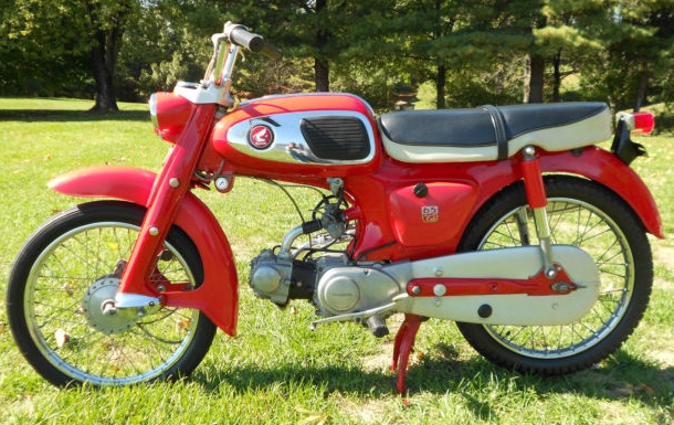
A 1964 Honda Sports 65
The BSA Beagle was largely the work of Edward Turner who was credited with the design of the famous Triumph Speed Twin and Ariel Square Four among others and who was, at this time, Chief Executive of the Automotive Division (included BSA, Triumph, Ariel, etc) of the BSA Group. In 1960 Turner undertook a tour of the Honda, Suzuki and Yamaha plants in Japan and may well have based the Beagle concept on what he saw during his visit. In this period, Japanese bikes dominated the lightweight market and, rather belatedly, BSA decided to try to compete. The Beagle was the end result but, unfortunately, only served to demonstrate the shortcomings that existed at BSA and ended up being a commercial failure.
Production of the BSA Beagle started in late 1963. It used a pressed steel frame with leading link front suspension similar to the Honda lightweight bikes. Although it could have used a much cheaper 2-stroke engine like the BSA Dandy, Turner decided to use a 75cc 4-stroke engine with 4-speed gearbox in order to give it much better fuel consumption. The engine shared a lot of features with the Triumph Tiger Cub engine from which it was derived but with a wet sump rather than a separate oil tank. A smaller 50cc version of this engine, involving only a change in cylinder bore size, was also used in the Ariel Pixie. As with the Honda lightweight machines, the engine was bolted on to the front of the lower part of the chassis.
The overall configuration of the OHV Beagle engine is shown and, like the Tiger Cub engine, the cylinder was slightly inclined in the forward direction. It was fitted with an AMAL Type 19 carburettor with integral fuel tap. The engine used a cast iron cylinder and aluminium cylinder head. In contrast with the Tiger Cub engine (and most unit BSA singles), the Beagle used separate inlet and exhaust rocker enclosures cast into the head with separate tunnels in the cylinder for the two push rods. The rockers had conventional adjusters for setting the tappet clearances. As with the later BSA unit single engines, the Beagle engine used an internal rack and pinion mechanism to operate the clutch together with an external horizontal lever at the top of the outer timing cover operated by cable.
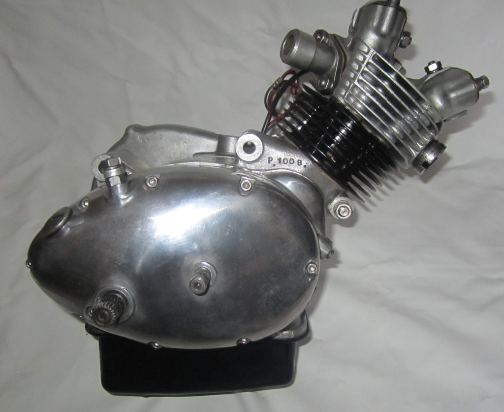
Right-hand view of Beagle engine
The internal view of the right-hand side of the engine with the outer timing cover removed is shown. On the left-hand side can be seen the Tiger Cub like kickstart quadrant and ratchet pinion on the end of the gearbox mainshaft. The gear change quadrant is also very similar to that of the Tiger Cub except that the return spring is on the outside of the inner timing cover rather than on the inside. On the right-hand side can be seen the single piston oil pump (no return side necessary with a wet sump engine) driven by the eccentric peg on the outside of the camshaft journal. This is different to the Tiger Cub which used a dual piston pump on the other side of the inner timing cover that was then driven by an eccentric peg on the end of the distributor drive shaft. Engine breathing took place via a hole from the crankcase to the oil pump enclosure and then via the outer timing cover into the moon shaped opening above the gear change quadrant. This is connected via a passageway across the engine to an outlet just in front of the engine sprocket.
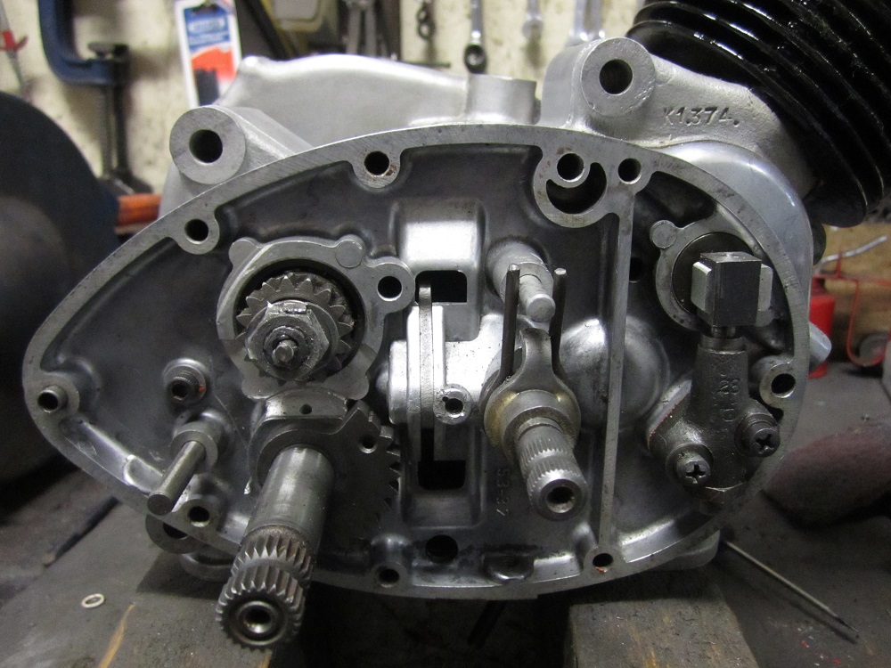
View of Beagle engine outer timing compartment
The left-hand side of the engine contains the primary drive and the electrical generator. The clutch is driven directly from the crankshaft gear and therefore does not use a primary chain as in the Tiger Cub or the unit BSA singles. The clutch uses an outer pressure plate which has friction inserts on the inside surface. The clutch has one other friction plate and two plain plates with the latter having teeth on the outside which engage with the engine gear. Four clutch springs are used to pull the plates together.
The clutch is unusual in that the end of the gearbox mainshaft pokes through the pressure plate and is supported via a needle bearing in the outer cover. The part of the shaft behind the pressure plate is slotted to allow a transverse metal bar in the slot to be pushed outwards by the actuating rod in the shaft which then pushes against the pressure plate thereby disengaging the clutch.
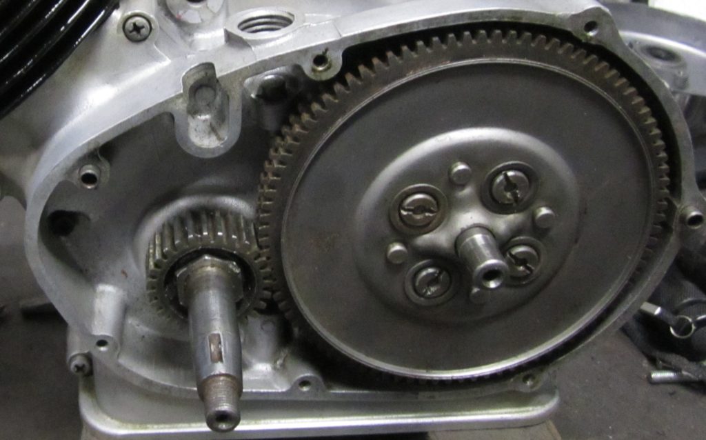
View of Beagle engine primary drive
In addition to the needle roller bearing in the primary cover to support the end of the gearbox mainshaft, the cover also houses a ball bearing that supports the end of the crankshaft. This means that there are 3 separate ball bearings supporting the crankshaft and 2 ball bearings and 1 needle bearing supporting the gearbox mainshaft. The reason for this number of bearings is presumably because the crankcases are too narrow to adequately support the crankshaft and gearbox mainshaft by the usual pair of bearings used in larger engines – hence the need for extra bearings to provide the required lateral stability.
The generator is mounted on the end of the crankshaft after the primary cover has been fitted to the crankcases. The Wipac generator consists of a stator and a rotor. The stator contains both a pair of lighting coils and an ignition coil generating the HT for the spark plug which it does by using a set of contact breaker points and a capacitor both of which are mounted on the stator. The points are adjusted by suitably rotating the crankshaft until the points become accessible through the cut outs in the rotor. The Wipac based electrical system used by the Beagle provides unregulated power to the lights and horn. The Beagle does not incorporate a stoplight but it does include parking lights, which are powered by a dry battery mounted inside the headlamp shell in a similar way to the earlier Dandy.
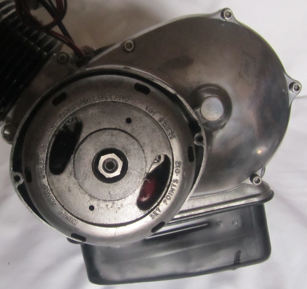
View of the Wipac generator containing the contact breaker points
The main problem with the Beagle engine was its poorly designed lubrication system. There were fundamental problems with the oil supply to the big end bearing which were similar in nature to that of the Tiger Cub and the early unit BSA singles. This was that oil reached the big end via holes in the crankshaft journal, which relied on a close fit with the feedholes in the crankcase casing in which it rotated. The plain big end bearing relies on good oil pressure that could be badly affected by wear in the crankshaft journal or the engine casing.
However, the more fundamental problem with the Beagle engine was that there was no direct oil supply to the rocker gear. The sales brochure at the time talked about lubrication of the top end of the engine by oil mist. There was, undoubtedly, oil mist generated in the crankcase by the revolving crankshaft but the thought that this could find its way in sufficient quantity up the narrow push rod tunnels in order to provide adequate lubrication for the rockers was clearly wishful thinking.
It is instructive to look at the design of the OHV Honda Super Cub engine of that period (prior to the OHC version in 1964). This did not actually use an oil pump but relied on an oil splash lubrication system, which seemed to work very effectively as demonstrated by the Maudes endurance trophy win. In this system, the oil in the engine sump is picked up by a cam-driven wheel, and fed through a hole in the right crankcase into the middle of the engine cases. This fills a small trough under the crankshaft that then feeds the crankshaft and top end. A small finger coming off of the big end of the connecting rod scoops oil into the big end rod bearing and also flings it toward the transmission and underside of the piston. Oil in this trough also feeds the cam bearings on which there is a spiral groove. This groove then feeds oil up to the top end of the horizontal cylinder and head via an external oil feed pipe. This proved to be a well thought out and effective lubrication system for these small OHV engines.
In contrast, it remains a bit of a mystery as to why the Beagle lubrication system was designed in the way it was. To some extent, it smacks of the engineering approach that Edward Turner was well known for – a very good engineer at the conceptual level but lacking in the fundamental engineering skills required to make things work properly in practice. In the case of the Beagle, the top end lubrication system seemed to be completely missing from the design but, on balance, it is more likely that Turner actually believed the oil mist lubrication system would be adequate. Not for the first time was one of his ideas shown to be unworkable in practice!
Unfortunately for BSA, the inherent lubrication problems with the Beagle engine led to premature big end and rocker box failures resulting in a large number of warranty claims. BSA refused to honour most of these claims and very much left it up to the Dealers to pick up the cost of putting right the problems. They, not surprisingly, refused to continue to stock the bike and production came to a premature end in early 1965 after just over a year of production.
In summary, the BSA Beagle was intended to show that BSA could compete successfully against the Japanese in the lightweight motorcycle market in the early 1960’s. Unfortunately, it demonstrated quite the opposite. The main problem was the poorly designed engine which was dubbed by at least one of the top BSA Dealers as ‘a first class example of Mickey Mouse engineering’.
My Beagle restoration
Having completed the restoration of a BSA Dandy earlier in the year, I then decided to restore a BSA Beagle despite its poor reputation. However, in contrast with the BSA Dandy, BSA Beagles rarely come on to the market – this year I’ve only seen one for sale and that’s the one I bought. The main reason for this is possibly because BSA made only about 4000 Beagles during 1963-65, whereas, closer to 25,000 Dandys were made over the 6 years that it was in production. However, it’s more likely to be that, because the Beagle engine did not last very long because of the lubrication problems, many were scrapped early on.
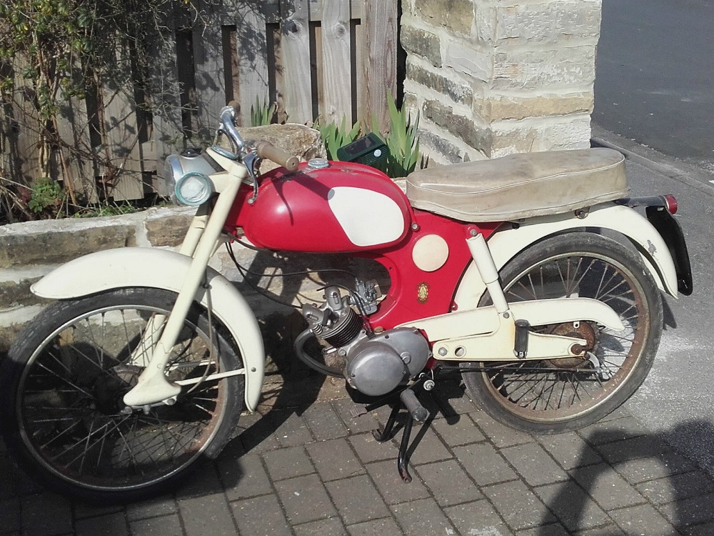
Unrestored 1964 BSA Beagle
I bought the above 1964 BSA Beagle from a person in Leeds who wanted to carry out a full restoration but, as usually happens, other projects then got priority. He, in turn, had bought it from another person who had started the restoration but had not finished it. This earlier person had collected a number of missing bits and had had a go at overhauling the engine and getting some of the paintwork done. He clearly had not touched the wheels and I was not particularly impressed with either the state of the engine or the paintwork.
The bike had the advantage of being more or less complete when I bought it, which is important for both a Beagle and a Dandy because spares are very difficult to get hold off. The best that can normally be done is to look out for second-hand spares which, surprisingly, seem to be slightly more plentiful for the Beagle than for the Dandy. Also, quite a few spares are available from the US since the Beagle was sold there as the BSA Starlite.
The Beagle was stripped down to its component parts and the small numbers of chrome parts were sent off to be re-chromed, including the handlebars and complete exhaust system. The silencer was in reasonably good condition but had an unsightly dent in its side. I attempted to fill this with braze material after removing the chrome coating but could not quite achieve a blemish free result. However, the chrome company finished off the job, possibly with a bit of copper coating and the result was a near perfect finish.
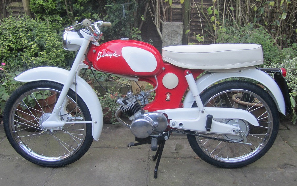
Much of the paintwork was in sound condition and, rather than stripping it completely, it was flatted down and any imperfections filled. The exception was the petrol tank that had paint peeling off the top and so all of its paint was stripped off. The tinware was repainted with BSA Royal Red and Ivory, although this was not a colour combination that the Beagle had left the factory with a far as I can see. The normal colour was Mist Green and Ivory. The colour combination chosen for my Beagle was that used for the BSA Starlite for the US market and which is far more attractive than the Green/Ivory combination.
The Beagle uses 19″ wheels with 2.25″ tyres. Unlike the Dandy with its small 15″ diameter wheels, 19″ WM1 chrome plated rims are readily available. After stripping both hubs and repainting in Silver, the wheels were rebuilt using new spokes and rims from Central Wheel Components Ltd. New rim tapes, inner tubes and then tyres were fitted to complete the restoration of the wheels. The seat pan was repainted in Ivory and was then taken to RK Leighton in Birmingham for a new cover.
Re-assembly of the BSA Beagle was largely straightforward although the parts book is slightly confusing in places, especially when trying to reassemble the rear axial. The most fiddly part of the re-assembly was replacing the front forks. The Beagle fork assembly consists of both fork legs welded on to the bottom yoke and a top-mounting bracket. The cone for the lower steering head bearing is mounted on the bottom yoke and the cone for the top bearing is mounted on to a separate small casting into which the top of the fork pivot stud is screwed. To assemble the forks on to the frame, first requires the fork assembly to be offered up so the lower bearing cup and cone mate . The fork pivot stud attached to the steering head casting must then be inserted so that the upper bearing cup and cone mate. This casting then has to be bolted to the front fork assembly via 2 x bolts that screw into a small strengthening plate and which has to be held in place inside the top of the fork assembly. The final stage of assembly is to add the nut onto the lower end of the fork pivot stud and to tighten it to remove any play in the steering head bearings. Ideally, re-assembly of the forks requires 2 people – how I managed it on my own is still a mystery!
The BSA Beagle uses a Wipac electrical system based on the use of a crankshaft generator containing both an ignition coil and a pair of lighting coils. The ignition coil provides the HT output to the spark plug and works in conjunction with a contact breaker housed next to the coils along with its capacitor. A previous owner had attempted to re-wire the bike but had not completed it by the time he sold the bike. The main part of the harness from the headlamp to the inside of chassis behind the plastic cover in its left-hand side was in good condition but the wiring to the rest of the bike needed to be remade.
Although I did not really need them, I managed to buy a box of Beagle/Pixie engine parts from a person in Liverpool who had been collecting them for a number of years. As they stood, these spares were more or less enough to enable me to build another complete engine as shown below. If you look closely at the engine number it can be seen that this started life as an Ariel Pixie engine but it is now fitted with a Beagle cylinder and piston, which is the only difference between the 2 engines. Although the actual engine in my Beagle required very little doing to it, the spare engine was missing a number of bearings and also oil seals that had to be individually sourced.
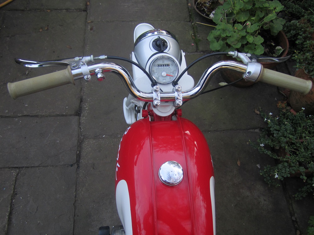
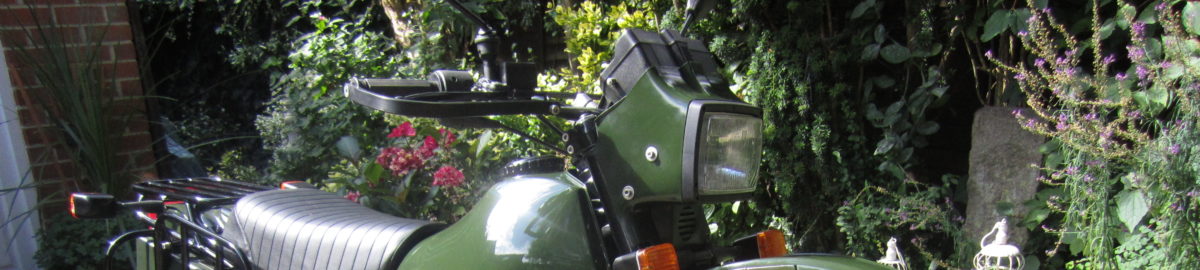
View of restored Beagle handlebar/headlight layout
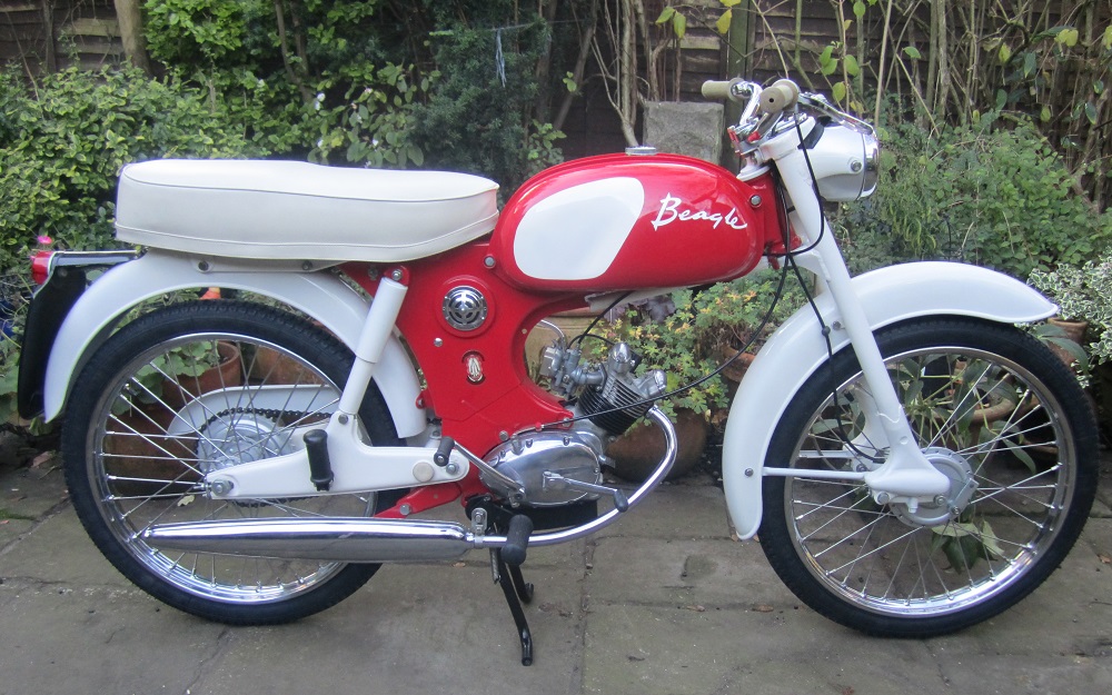
Right-hand side view of restored 1964 BSA Beagle
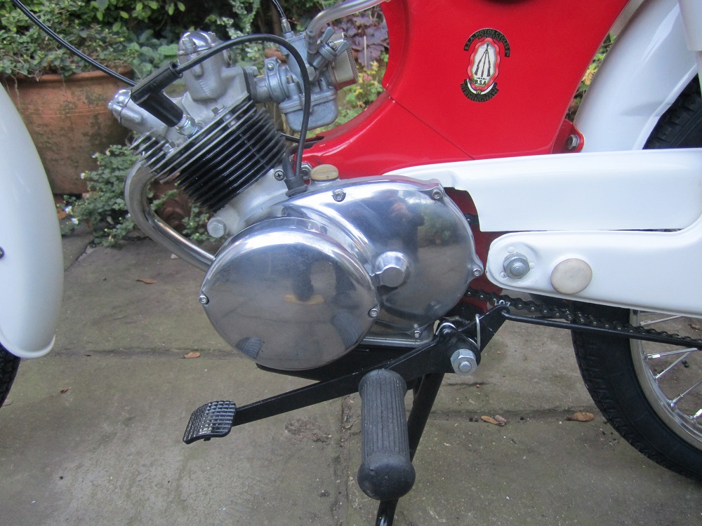
Close up of engine mounting in restored BSA Beagle

Left-hand side view of restored 1964 BSA Beagle
The biggest issue with running a Beagle on the road is the lack of lubrication to the rocker spindles. Common sense will tell you that the top end ‘oil mist’ lubrication system described by BSA in their sales brochure was nothing more than wishful thinking. This more than anything else was responsible for the bike’s poor reputation and early demise.
To properly run the Beagle on the road, two approaches are possible for overcoming the top end lubrication problem. The first is to take off the rocker covers before each outing and to then liberally coat the moving parts in engine oil. With luck, this will minimise the wear over moderate length outings.
A better approach would be to provide proper lubrication for the top end. A couple of possible solutions come to mind but both would involve running an oil supply line to the rocker boxes. The neatest solution would be to follow the approach adopted for the Triumph Tiger Cub and BSA unit singles and to do this via an oil banjo connection to the ends of both rocker spindles. These would, in turn, need to be custom manufactured with hollow centres and outlet holes under the rocker bearing surfaces.
The simplest way of providing the oil supply would be from a total loss oil reservoir that could be mounted above the engine in the pressed steel frame. This would need to be carefully set up to provide the minimum flow rate needed and, of course, the oil level in the sump would need to be adjusted after each ride out.
A more sophisticated approach to providing the rocker oil supply would be to fit a small electric pump inside the pressed steel chassis that could draw up oil from the sump and then pump it at low pressure to the rockers. This way, the problem would be completely solved and premature rocker failure would be eliminated.
In summary, the BSA Beagle is now a very rare beast and does not often come up for sale. To modern eyes, it’s styling is not that bad and the layout of the bike is otherwise fairly conventional. Unfortunately, the poor level of engineering effort that went into the engine was its Achilles heel making it a challenge to keep this lightweight bike running on the road.
BSA Beagle Specifications
- Year: 1964-5
- Engine: Single cylinder, 4-stroke
- Starting: Kickstart
- Capacity: 75 cc
- Bore/Stroke: 48 x 42 mm
- Compression Ratio: 9.5:1
- Max Power: 5.0 bhp
- Carburettor: AMAL Type 19 carburettor
- Cooling: Air cooled
- Lubrication: Wet sump
- Ignition: Magneto and contact breaker
- Electrics: AC flywheel generator with dry battery for parking
- Transmission: 4 speed, multi-plate dry clutch
- Final Drive: Chain
- Front Suspension: Leading link with coil spring but no damper
- Rear Suspension: Coil spring with damper
- Front Brake: 4.5″ drum brake
- Rear Brake: 5″ drum brake
- Wheel Base: 47″
- Seat Height: 29″
- Front Tyre: 2.25 x 19 inch
- Rear Tyre: 2.25 x 19 inch
- Ground Clearance: 7.5″
- Dry Weight: 140 lb
- Oil: 1.24 pints
- Fuel Tank: 2 gallons
13,918 total views, 3 views today