
Following the success of Edward Turner’s Triumph 5T Speed Twin in 1938, BSA produced the 500 cc A7 in 1946 with Val Page as Chief Designer which was the company’s first parallel twin motorcycle. This used a long stroke, semi-unit engine with bore and stroke of 62 mm x 82 mm. However, when Triumph produced the 650 cc 6T Thunderbird in 1949 for the US market, BSA were forced to offer their own 650 c A10 later that year. In terms of BSA model years, the A10 was introduced in model year 1950 which extended from 1 August 1949 to 31 July 1950. The A10 used a re-designed and improved version of the A7 engine with the design work carried out by Bert Hopwood who had been enticed away from Norton in 1948. The A10 engine used a bore and stroke of 70 mm x 84 mm to give a capacity of 646 cc. This engine design was then used as the basis for a revised shorter stroke A7 engine in 1951.
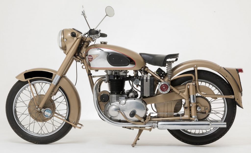
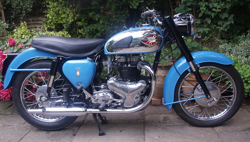
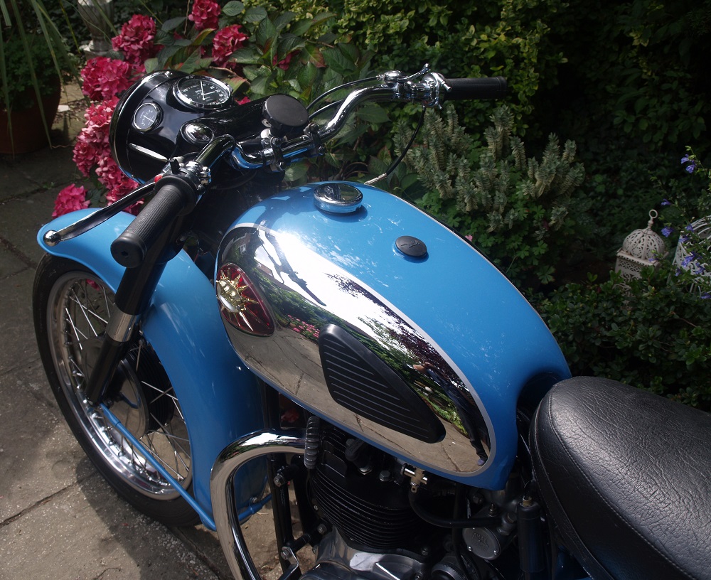
When launched, the BSA A10 was available in black and chrome or silver beige as shown below with the latter gold-like colour giving the A10 its Golden Flash name. The A10 was available in either a rigid or plunger frame with the latter having a bolt-on rear sub-frame. Front suspension was by telescopic forks with external springs which came with metal tubular covers extending to the top of the fork legs. It was fitted with a 3.25″ x 19″ front wheel with single sided 8″ drum brake and a rear wheel size of 3.50″ x 19″with a quickly detachable (QD) ‘Crinkle Hub’ and 7″ drum brake. Operation of the rear brake was via a left-hand brake pedal and operating rod to the drum brake on the same side of the bike. The A10 used a headlight cowl around the headlight shell which contained the speedometer, ammeter and lighting switch. A friction steering damper was fitted below the steering head with an adjuster knob at the top.
The mudguards fitted were fairly conventional in design but the rear mudguard was hinged to allow easier removal of the rear wheel. A four gallon petrol tank was fitted with brackets at the front and rear to allow it to be bolted to the frame with chrome panels and winged metal BSA badges and rubber knee pads. An oil tank was mounted on the right-hand side behind the engine with a tool box mounted low down behind it. On the opposite side to the oil tank was mounted a combined air filter box and battery carrier with the battery exposed to the elements!
The A10 was fitted with 6 V electrics using a Lucas E3H (later E3L) dynamo to provide a charging current for the battery via a Lucas MCR2 mechanical regulator mounted under the saddle. Engine ignition was provided via a Lucas K2F magneto. The handlebars were fitted with conventional front brake and clutch levers together with a choke lever and an ignition control lever for the magneto. In addition, it was fitted with a horn push button and ignition cut-out button.
The A10 continued with the plunger frame until 1954 when it was changed to a swinging arm frame and twin rear shock absorbers. The main reason for the change was that BSA became concerned that wear in the plunger suspension units resulted in uncertain handling issues especially with the higher performance A10’s. In contrast, the swinging arm setup resulted in more controlled movement of the rear wheel independent of any wear in the rear shock absorbers.
With the change to a swinging arm frame, the original toolbox could no longer be accommodated in its original position and therefore a new toolbox was mounted on the opposite side to a revised oil tank. Inside the toolbox was housed the Lucas regulator. At the front, between the oil tank and toolbox was mounted an air filter enclosure connected to the AMAL carburettor via a short rubber hose. Behind the air box was mounted a battery carrier which was accessed after removing the seat. Other changes to the earlier plunger models was the deletion of the hinge in the rear mudguard and a change to a central fixing bolt for the petrol tank which now had round BSA badges rather than the earlier winged badges.
The A10 Golden Flash remained largely unchanged until 1957 when 8″ full width front and 7″ rear wheel hubs were introduced. To provide a detachable rear wheel that could be removed while leaving the chain sprocket in place, the drum brake was mounted on the right-hand side of the bike. This necessitated the mounting of the brake pedal on a cross-shaft that ran within the swinging arm spindle to a lever on the right-hand side of the bike that then operated a cable to the back brake lever.
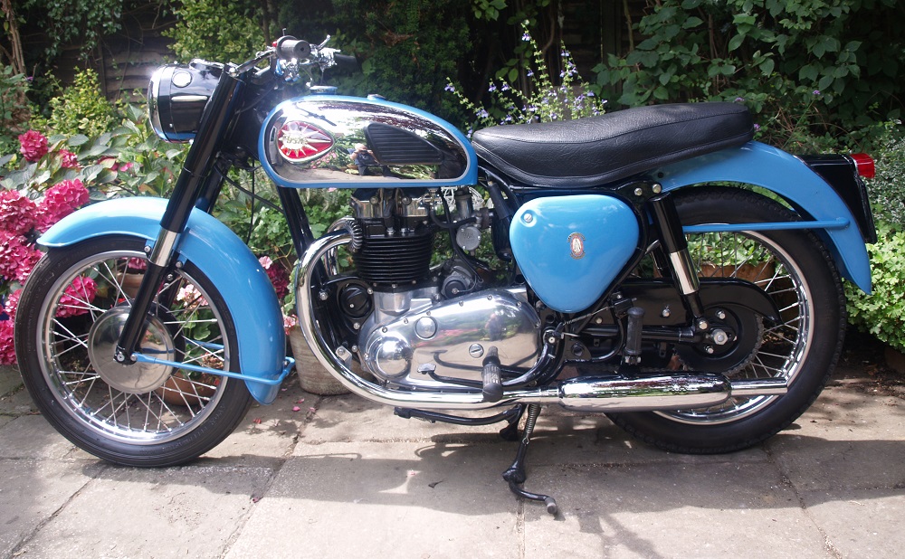
In 1958, cosmetic changes were made to the Golden Flash that included the deletion of the headlight cowl to leave a headlight shell fixed rigidly to the upper fork cover. Like later BSA motorbikes, a support ring for the headlight unit was fixed to the shell and provided the means for adjusting the beam pointing.
A10 Engine Design
With the launch of the triumph Speed twin in 1937, Edward Turner provided the blue print for most of the British twin cylinder motorcycle engines that followed. These were all 360 deg, overhead valve (OHV), dry sump engines using a separate external tank for the lubricating oil. However, in contrast with the Triumph twins with their separate inlet and exhaust camshafts and pair of pushrod tubes, the A10 used a single camshaft with a pushrod tunnel cast into the rear of the cylinder block. Four pushrods were used with cam followers at their lower ends. The cylinder head was made in cast iron and incorporated the inlet manifold for the single AMAL 276 Monobloc carburettor. In contrast with the earlier BSA A7 with its two separate rocker boxes, the A10 was fitted with a single alloy rocker box housing the inlet and exhaust rockers. The compression ratio for the Golden Flash engine was 7.25:1 and its output power was 35 bhp.
The A10 originally used a built up crankshaft that ran in a plain metal bearing on the timing side and a roller bearing on the drive side. The single camshaft was housed within the crankcase above and behind the crankshaft. The crankshaft used plain big-end bearings and alloy conrods with split ends. The timing gears were housed on the right-hand side of the crankcase under the inner timing cover. The pinion on the crankshaft meshed with an idle pinion immediately above it which in turn meshed with the camshaft pinion. This then meshed with the drive pinion for the magneto which was mounted behind the rear of the crankcase. The magneto pinion also incorporated an auto advance timing unit. On the right-hand side, the crankshaft also included a worm gear that drove the geared oil pump that was bolted on the crankcase below it.
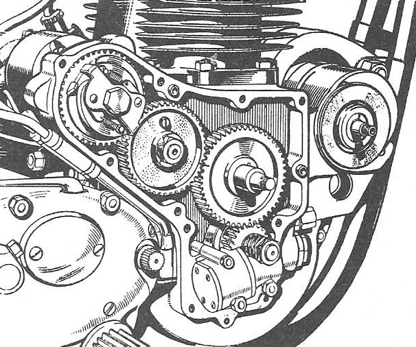
Engine breathing was via a top hat device that rotated in the inner timing cover and was pegged against the outside of the camshaft pinion. A cork gasket or washer was fitted between the pinion and the breather whose thickness had to be carefully chosen to control the gap between the top hat flange and the inner timing cover. The top hat tube had a small hole in the side of it that aligned with the end of a tube in the inner timing cover which, once per revolution, connected the timing enclosure to a gallery in the crankcase behind the camshaft with an exit hole on the left-hand side at the back of the crankcase through which the engine breathed.
Within the outer timing cover, the crankshaft was fitted with a sprocket that then drove the dynamo sprocket mounted in front of the engine via a single chain. Rotating the eccentrically mounted dynamo enabled the slack in the chain to be carefully adjusted.
The pre-swinging arm A10’s used a 4-speed gearbox bolted to the back of the engine which is sometimes referred to as being of semi-unit construction. In this arrangement the inner part of the chaincase was cast integral with the left-hand crankcase with the outer cover bolted to it. A duplex primary chain was employed with a slipper tensioner used to control the slack. A 6-spring clutch was used with 5 pairs of drive and driven plates. The shock absorber for the primary drive was via a cush drive consisting of a spring loaded sleeve whose pair of cams engaged similar cams on the outside of the crankshaft sprocket .
The main changes to the engine came in 1954. With the introduction of a swinging arm frame, the engine was changed so that the gearbox was no longer bolted to the back of it and the pre-unit configuration used with bolt-on chaincase and with the gearbox having to be tilted back or forth to correctly adjust the single primary chain. This then required the rear chain to also be adjusted. At the same time, the gearbox internals were changed to include a new gear change quadrant design and the clutch design was also modified.
A10 Models
The rigid framed A10 Golden Flash continued as an option up to the start of the 1954 model season, whereas, the plunger version continued up to and including the 1957 season. The swinging arm A10 that was introduced in 1954 continued in production up the end of the 1963 model year, by which time, the unit construction A65 had been in production for a year.
The first new A10 model was the A10 Super Flash introduced in 1953 for the US market, initially with a plunger frame and then, in 1954, with a swinging arm frame. The main changes compared with the basic A10 was the use of a sportier ‘356’ camshaft and the use of an AMAL TT carburettor which raised the output power to 40 bhp. It was fitted with a 2.5 gallon Gold Star tank and chrome mudguards.
The first sportier model introduced for the UK market was the swinging arm A10R Road Rocket in 1955. The A10R featured an alloy cylinder head, the use of the ‘356’ camshaft and an AMAL TT carburettor. The compression ratio of the engine was the same as the Golden Flash at 7.25:1 and the output power was 40 bhp. The A10R engine made use of the so-called ‘thick flange’ cylinder and larger big-end journals, both of which were designed to increase the strength of the engine. Like the A10 Super Flash, the A10R also featured chrome mudguards.
The A10R continued until the end of the 1957 season when it was replaced by the A10 Super Rocket which continued in production until being phased out with the other A10 models at the end of the 1963 season. The A10 Super Rocket used an alloy head with large valves and the compression ratio was raised to 8.26:1 increasing the output power to 43 bhp.
Also introduced during the 1957 season was the A10 Spitfire Scrambler. This was produced by a request from US West Coast distributor, Hap Alzina, who wanted a BSA bike that could compete in desert racing against the Triumph twins. Originally, it used a A10R engine with modified head to accept a 1 1/6″ AMAL Monobloc carburettor with the compression ratio raised to 9:1 and a ‘357’ race cam fitted. The A10S was fitted with an exhaust system without silencers, a 2-gallon US petrol tank but no lights . In 1958, it was fitted with the ‘big valve’ head from the A10SR. The A10S remained in production until the end of 1963 with last year of production being based on the Rocket Gold Star engine and frame.
The final model of the A10 was based on the hybrid bike produced by Banbury based Gold Star expert Eddie Dow who mated an A10 Super Rocket engine with a BSA Gold Star frame. This was so well regarded that BSA decided to put it into limited production as the Rocket Gold Star starting in 1962. With a compression ratio of 9:1 and the use of a ‘357’ race cam and 1 5/32″ AMAL Monobloc carburettor, output power was raised to 46 bhp. With options such as an AMAL GP2 carburettor and siamesed exhaust system and RRT2 close ratio gearbox, output power could be raised to 50 bhp.
The main reason that BSA put the Rocket Gold Star into limited production in the same year that the unit A65 was introduced may have had a lot to do with using up old stock of Gold Star frames and A10 engines. Nevertheless, whatever the true reasons, the Rocket Gold Star marked the end of an era for the BSA large capacity pre-unit twin and is now, with the Gold Star, one of the most sought after BSA motorbikes ever produced fetching very high prices.
My A10 Restoration
My A10 Golden Flash was built in 1961 and, rather than hiring a motorcycle trailer to collect it, I decided to ride it home 150 miles from near Burton-on-Trent. Unfortunately, it rained incessantly on the way home making this one of the most miserable trips I have ever made on a motorcycle although the A10 performed admirably.
 As seemed to be the case with many of my bikes, I bought the A10 a long time ago but it was many years later before I started to restore it having been distracted into restoring a number of single cylinder bikes in the meantime. The A10 was in reasonable working condition when I bought it but I gave it a full nuts and bolts restoration.
The bike was completely disassembled and the frame and attachments sent away for powder coating. The headlight shell and nacelle, front fork sliders and rear number plate mounting were all spray painted in gloss black. The rest of the bike was spray painted in BSA Nutley Blue and finished in a clear coat. Most of the painting was carried out a few years ago except for the petrol tank which, at the time, I did not have necessary skills to carry out. However, my spray painting skills are now up to the job and I completed painting the petrol tank a week or so ago finishing it with a 2K clear coat which provides a petrol proof coating. With new pear shaped BSA badges and new knee pads, the tank now shows off the bike to good effect.
The wheels were completely rebuilt and, in this case, I actually got Central Wheel Components to do the work rather than, as is now the case, I do the rebuilding myself. The front forks were overhauled with replacement stanchions and new bushes and seals. The rear shock absorbers were beyond salvage and were therefore replaced by new units.
All the chrome plated components were sent off to be re-chromed including the complete exhaust system which was in reasonable condition with no damage to the silencers. The petrol tank was also re-chromed after any dents were removed and the tank panels polished after suitable copper plating.
The engine was completely rebuilt with new bearings and seals throughout including the big-end shells. The only issue with the engine was that many of the cylinder fins were badly damaged because of rust and I therefore decided to get a replacement cylinder. This was re-bored with new pistons. The valves and springs were replaced and the valves and head re-ground. The primary chain was replaced along with the clutch plates and springs. The gearbox was completely re-built but was in reasonable condition.
The bike’s electrics and wiring harness were all in good condition when I bought the bike and required very little attention. All the control cables were replaced. The seat was restored by RK Leighton in Birmingham although they forgot to use white piping around the top of the saddle which is a bit of a pity.
Although slightly old fashioned in appearance, the BSA A10 is nevertheless a handsome looking motorbike and is well engineered. In its more sportier forms, especially the Rocket Gold Star, the A10 was equal to any of it competitors including the pre-unit Triumph T120 650 cc Bonneville. Unfortunately, its replacement, the BSA A65, failed to make the same impact because of its slightly bulbous unit engine that resulted in a somewhat portly motorcycle which lacked the style of its main competitor, Triumph.
BSA A10 Golden Flash Specifications
- Engine: Twin cylinder, 360 deg, OHV
- Starting: Kickstart only
- Capacity: 646 cc
- Bore/Stroke: 70 mm x 84 mm
- Compression Ratio: 7.25:1
- Max Power: 35 bhp
- Carburettor: AMAL 276 Monobloc (1950-57), AMAL 376 Monobloc (1958-63)
- Cooling: Air cooled
- Lubrication: Dry sump
- Ignition: Coil and contact breaker points
- Transmission: 4 speed foot shift
- Final Drive: Chain
- Front Suspension: Coil spring and hydraulically damped
- Rear Suspension: Coil spring and hydraulically damped
- Front Brake: 8″ single side drum (1950-57), 8″ full width drum (1958-63)
- Rear Brake: 7″ single side drum (1950-57), 7″ full width drum (1958-63)
- Frame: Rigid (1950-53), plunger (1950-57), swing arm (1954-63)
- Wheel Base 54.75 inch
- Seat Height: 32 inch
- Front Tyre 3.25 x 19 inch
- Rear Tyre: 3.50 x 19 inch
- Ground Clearance: 8 inch
- Dry Weight: 395 lb
- Fuel Tank: 4 gallons
- Oil Tank: 5.5 pints
BSA A10 Parts Suppliers
Most A10 spare parts are relatively easy to get hold of with many good suppliers easily found on the internet. Two of the larger suppliers of BSA parts are Burton Bike Bits and Dragonfly Motorcycles.
18,755 total views, 2 views today