The 250 cc BSA C25 Barracuda was first introduced in model year 1967 (1 August 1966 to 31 July 1967) to replace the C15 that had been in production since 1959. It used a modified version of the C15 engine and a modified version of the welded duplex frame first introduced in 1963 in the C15 competition model. However, the Barracuda was short lived and, later in 1967, it was renamed the B25 Starfire with only minor changes between the two models including the addition of a pillion passenger grab rail for the B25. This change in nomenclature was due to the fact that the C15 should have started life as a B-Series 4-stroke OHV model rather than a C-Series 4-stroke side valve model and this was a belated attempt to rationalise the BSA model range.
The B25 engine was based on that of the C15 with the same bore and stroke of 67 mm x 70 mm but with a compression ratio raised to 10:1. It made use of a 928 AMAL Concentric carburettor with a pancake air filter attached. It made use of a similar engine bottom end to the C15 including an end-fed crankshaft and the use of timing side ball bearing as in the 1967 C15 which was a vast improvement on the original design with plain timing side bush. However, rather than the roller big-end bearing used on the later C15’s, the B25 used plain big-end bearings requiring split conrod ends.
The other main changes to the B25 engine concerned the top end. Unlike the round barrel C15 engine, the B25 used squared off fins for the barrel and cylinder head. It also used a push rod tunnel cast into the barrel rather than the separate pushrod tube that was a characteristic of the C15. Other changes included the use of eccentric rocker spindles which could be rotated using a screw driver once the oblong inspection cover was removed to adjust the valve clearances. This removed the need for the normal type of screw adjuster on the ends of the rockers. With the use of this type of spindle, it was necessary to move the rocker oil supply from the left-hand end of the spindles as on the C15 to an inlet pipe on top of the cylinder head.
Original B25 Model (1967-1970)
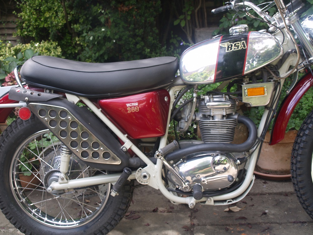
The C25/B25 welded duplex frame made use of duplex tubes running under and behind the engine which met the top tube in front of the seat. The swinging arm used silent block bushes together with a large spindle that bolted between the frame brackets on either side. The frame was equipped with both a centre stand and a side stand. Rod damper front forks were used with two-way damping that were introduced in 1967 to replace the earlier, so-called, heavyweight forks used on earlier BSA models. Rear suspension was via twin Girling shock absorbers. Front wheel size was 3.25″ x 18″ with 6″ half width brake hub originally used. This was changed in 1968 to a 6″ full width hub and in 1969 to an 8″ full width, twin leading shoe brake hub. Rear wheels were 3.50″ x 18″ with 7″ quickly detachable (crinkle) hub.
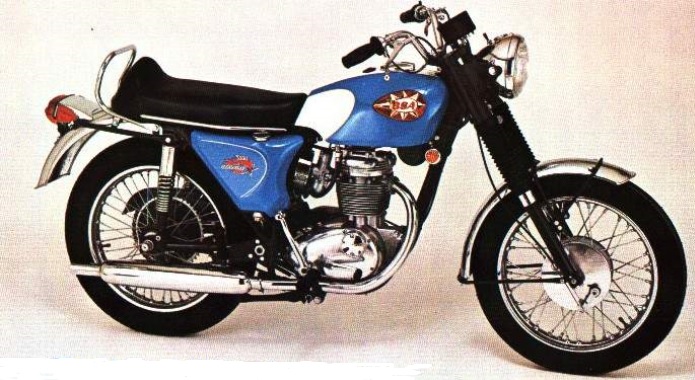
The B25 originally used a glass reinforced plastic (GRP) petrol tank with narrower, sculptured rear ends for the riders knees that was changed in later 1969 to a steel tank. The tank incorporated pear shaped plastic BSA badges but with no knee pads. The B25 initially used a GRP oil tank with integral cover but this was later changed in 1969 to a steel tank and separate GRP cover. The B25 used a battery carrier bolted to the left of the oil tank with a separate GRP cover.
The B25 used chrome plated mudguards front and rear with tubular stays. A separate chrome plated headlight unit was used which incorporated an ammeter, a lighting switch and a main beam warning light. The ignition switch was positioned on a frame bracket just in front of the left-hand battery cover. The B25 used 12V electrics with a Zener diode used for controlling the battery charging. It used a speedometer mounted inside a rubber boot fixed to a bracket above the fork top yoke.
Oil-in-Frame B25 (1971)
The original welded duplex framed B25 continued until the end of the 1970 season when it was replaced by the so-called Oil-in-Frame (OIF) version that was the result of the work of the notorious BSA Umberslade Hall Design Centre. To some extent, the OIF was a solution to a problem that did not exist since there was absolutely nothing wrong with the existing version of the B25 and the OIF design resulted in no obvious advantages.
The new frame was painted BSA Dove Grey which was not to everyone’s taste. It made use of slim Marzocchi type forks in which the whole inside length of the lower legs formed the bearing surface against the fork stanchions. This is in contrast with all the earlier forks which used a pair of internal bushes inside each fork leg. The steering head bearings used taper roller bearings top and bottom. Rear suspension was via twin Girling shock absorbers. Unlike the original B25, the swinging arm pivoted on needle roller bearings. The swinging arm bolt also passed through elongated holes in the frame brackets on either side and snail adjuster incorporated to allow the swinging arm pivot point to be moved back or forth to provide adjust of the rear chain tension. The rear wheel spindle bolted solidly into holes in the end of the swinging arm. The OIF B25 was equipped with a study sidestand but the centre stand was an optional extra.
The B25 OIF used 12 V electrics but, because there was no room under the seat, the main electrical components were mounted inside an electrics box suspended just in front of the hot exhaust rocker box. The electrics box housed the coil, condenser, rectifier, Zener diode with the ignition switch on the left-hand side of the box. In order to try to stop the engine vibration from destroying the contents of the electrics box, it was suspended via rubber buffers from the frame. The OIF B25 used Lucas switch units incorporated into the clutch and front brake mounting brackets. The left-hand switch unit incorporated the headlight flasher and main beam switch together with the horn button. The right-hand switch unit incorporated the direction indicator control and the engine cut-out switch.
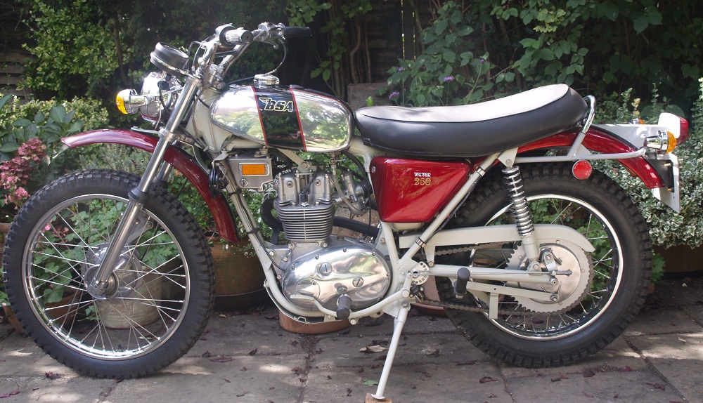
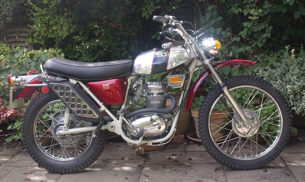
There were two versions of the OIF B25: the B25SS Street Scrambler and the B25T Trail. The two bikes shared many features including the frame and suspension and the exhaust system including the distinctive large lozenge shaped silencer with stainless steel perforated heat shield for the pillion passengers right leg. Both used a 928 AMAL Concentric carb that connected to a air filter box on the left-hand side incorporating a large round paper filter. The air filter was enclosed by a metal cover that attached to the frame. On the opposite side of the bike was a similar cover with the battery carrier behind it. Both B25 models used identical headlights supported on wire bracket either side via the front indicator stalks. A light switch was incorporated into the headlight shell together with a number of warning lights (indicators, oil pressure and main headlight beam). The rear indicators were mounted on the rear light bracket. The rear mudguard was braced by a tubular stay which included a grab rail loop for the pillion passenger.
Both models used conical hubs front and rear. The B25SS used a 3.25″ x 18″ front wheel with 8″ twin leading shoe brake. It used an unsprung front mudguard held in place by rather weak wire stays which were rubber mounted off the fork sliders. A 3.50″ x 18″ rear wheel was used with 7″ drum brake. In contrast the B25T used a narrow 3.00″ x 20″ front wheel with 6″ single leading shoe brake. It used a sprung front mudguard mounted on the steering lower yoke via a large bracket. It used a 4.0″ x 18″ rear wheel with the same 7″ drum brake as the B25SS. The B25SS used a 3 gallon steel petrol tank while the B25T used a 2 gallon aluminium tank. The B25T was also fitted with a sump guard.
The OIF B25’s used essentially the same engine as the earlier B25 with the same 10:1 compression ratio. The main difference between the B25SS and B25T engines was the use of a lower ratio gearbox in the latter. All the B25’s used a plain big-end bearing but, for the OIF B25, a separate paper cartridge oil filter was incorporated within the lubrication system to help to preserve the life of the bearing. This filter unit was mounted on one of the engine plates at the rear of the engine.
My B25 Restoration
I bought this particular 1971 B25T is reasonable complete condition and then performed a full nuts and bolt restoration on it. The frame was powder coated in BSA Dove Grey by a firm in Redditch which carried out work for the National Motorcycle Museum and therefore had already acquired the correct frame paint for the BSA OIF models. At the time, my painting skills were not up to painting the Candy Red used on the OIF B25 and so I got the side panels and mudguards painted professionally.
New front fork stanchions were used and the front fork legs were fully polished rather than finishing them in their rough cast and silver painted state as they came out for the factory. The rear shocks were in useable condition but were repainted in Dove Grey and the springs re-plated. Both wheels were rebuilt using stainless steel rims and spokes. The original finish on the conical hubs was rough cast and then painted because this was a cheaper manufacturing approach from BSA. However, with bare hubs available before the rebuilds, I polished the hubs to produce a much better appearance for the bike. The only real difficulty with restoring the wheel was to decide was size of front wheel to use. This was originally 20″ but, since that size of off-road tyre was not available when I carried out the restoration, I switch the size to the 21″ in line with modern off-road motorcycles.
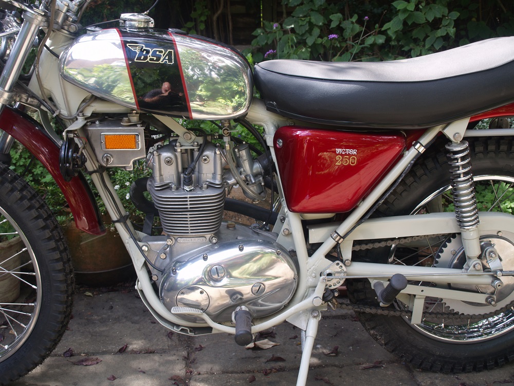
All the electrics and components were renewed on the bike except for the original Lucas handlebar switches which were in reasonable condition. The Aluminium petrol tank was slightly dented in a number of places and was therefore sent off to Motorcycle Dent Removal for these to be expertly removed. The tank was then polished and painted.
The engine was in reasonable condition but was completely rebuilt with new bearings and seals used throughout. The valves were replaced and their seats re-ground. The cylinder was given a rebore and new piston and the top of the engine vapour blasted. The clutch plates and primary chain were replaced and the chaincase and timing cover polished to a high shine.
I both OIF B25’s are handsome looking bikes, especially the colour scheme of the B25T and its 21″ front wheel and off-road type sprung mudguard. Although I have no intention of riding it, I think the B25T would make a good trail bike with its wide handlebar and relatively light weight. Although not hugely powerful, the B25 engine should have the performance for an enjoyable bit of trail riding.

BSA B25T Specifications
- Engine: Single cylinder, OHV, 2-valve, 4-stroke
- Starting: Kickstart only
- Capacity: 247 cc
- Bore/Stroke: 67 x 70 mm
- Compression Ratio: 10:1
- Max Power: 25 hp
- Carburettor: AMAL 928 Concentric carburettor
- Cooling: Air cooled
- Lubrication: Dry sump
- Ignition: Coil and contact breaker points
- Transmission: 4 speed foot shift
- Final Drive: Chain
- Front Suspension: Coil spring and hydraulically damped
- Rear Suspension: Coil spring and hydraulically damped
- Front Brake: 6 inch drum single leading shoe
- Rear Brake: 7 inch drum single leading shoe
- Frame: Oil-in-Frame (OIF)
- Wheel Base: 54 inch
- Seat Height: 32 inch
- Front Tyre: 3.00 x 20 inch
- Rear Tyre: 4 x 18 inch
- Ground Clearance: 7.5 inch
- Dry Weight: 130 kg
- Fuel Tank: 2 gallons
- Oil Tank: 4 pints
BSA B25 Parts Suppliers
Some B25 spare parts are relatively easy to get hold of with many good suppliers easily found on the internet. Two of the larger suppliers of BSA parts are Burton Bike Bits and Dragonfly Motorcycles.
19,023 total views, 4 views today

